Marc's K8000 robot page

last update: 02/01/2010
First some history of my robot project

1) First I started with what I expected from this project:
- the robot should be easy adaptable and extendable (future proof), for both software and hardware
- learn linux (as it is more and more coming up in the SW world)

=> the robot should not be a 'small robot on wheels with microprocessor', but more a PC on wheels.

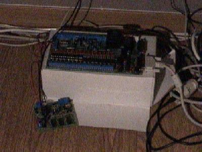
2) In an (Velleman) electronics magazine I saw an electronics project "K8000" (an I/O card that can be connected to the parallel port of a PC) and "K8005" (a stepper motor card that can be connected to the K8000). When looking at internet I found several K8000 sites, with a lot of information (a/o a Linux driver for these cards). So I bought these and soldered them.

To test them, I connected the K8000 and 2 K8005 boards to my PC (running both Windows and Linux, more about this later). The test succeeded (i.e. the boards were correctly soldered in 1 time!).


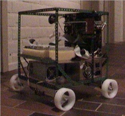
3) At the "HCC beurs" (a PC market) I found a Pentium motherboard with RAM and CPU. All I had to do is put all these boards together. From my grandmother I received a long long time ago some meccano. Ideal for this job (since one can extend it easily).

4) Now I had to add some wheels. At a model shop I found them; with some tubes etc. I was able to make 2 independent wheels (so it can turn left and right).


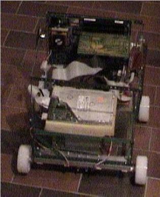
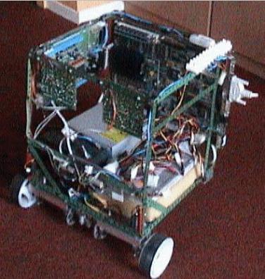
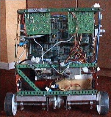
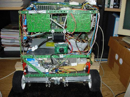
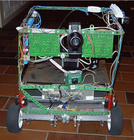
5) After putting it all together, this was the result:


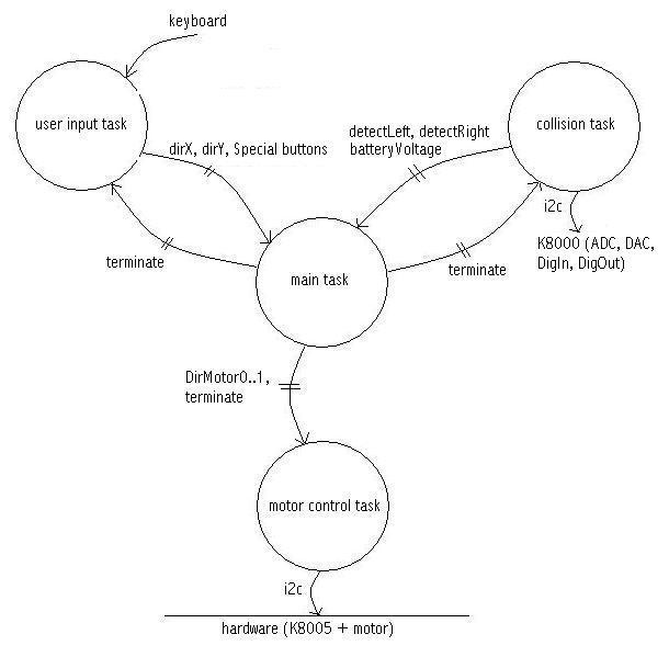
6) So now the hardware was ready, now I had to make some software for it. Because I'm a software engineer and my intension was to learn more from Linux, I made a beautiful software architecture with some processes, queues and semaphores (see more at point 16 below). After some debugging (with my first steps of DDD, the Linux debugger) I got it running (when the wheels were not touching the ground) !!! What a headaches I had with how to exit processes in a good way ;-).
But then another problem came up: the stepper motors that were delivered with the K8005 (Ming Jong ST28) were not strong enough (i.e. the torque was too low). With some help of the Yahoo K8000 community (especially Jukka Piepponen) and a colleague (Henk van Gijn) I have some clues of what the specifications of my stepper motors should be. (continued at 8.)

7) On my own PC I noticed that the RAM modules had some faults. Because I run both Windows and Linux on my own PC, and on the "PC of the robot" (also a Pentium running roughly on the same speed) only Linux and for Linux there is a BadRam patch available, I wanted to swap memory modules. Result: I blew up the motherboard of the robot (I inserted one/multiple RAM modules inverted, causing a short circuit that made the RAM socket(s) useless). So I bought a new "cheap PC" on E-Bay for the robot and installed it.

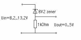
8) In a local second hand shop I saw 2 old HP Desk jet 500+ printers (very cheap: EUR 2,50 a piece). I knew there were stepper motors inside and hoped that they would be sufficient. When I opened them, there was also a gear (that I used) and a DC motor. When I put everything together the torque was not enough, but I didn't exploit the full potential of the stepper motor (a Minebea PM55L-48). My colleague Henk van Gijn made an electronic drawing to supply 12 Volts/0.6 Amp per coil. This worked, but because the motor was all the time powered, it became quite warm. So he added some extra stuff to the drawing, so the motor is only powered when the robot should drive; when it is parked the power over the motor is switched off (through a FET). This works fine.

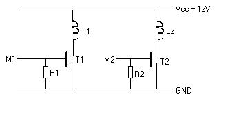
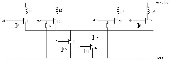
Here are the drawings:


Simple drawing


Advanced drawing


R1..R4 = 1k8
R5, R6 = 4k7
R7 = 18 Ohm, 10 Watt
T1..T6 = BUZ73
L1..L4 are the stepper motor coils, see the K8005 manual for details.
M1..M4 are connected to the K8005
A..B are connected to the K8000 (digital output, connect them like a TTL output as described in K8000 manual). drive: A=1, B=0; park: A=0, B=1; off: A=0, B=0.


These drawings are for 1 motor, so typically you should have everything double.

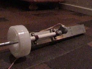
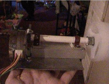
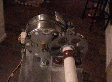
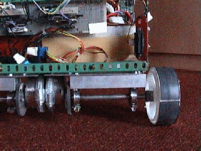
9) I noticed that the wheels (as you can see in the pictures they are made of plastic) didn't have a lot of grip on the floor. To overcome that, I cut the tube of a bike and glued it with adhesive tape to the two wheels that are connected to the motors. This works very good.

10) At the moment the robot can move, but not with a lot of torque (=force) and only forward/backward (left/right is not possible). The robot wheels are not optimized (for minimal friction), so that is my next goal: adding high precision bearings (idea from Jukka Piepponen).
Here are two pictures of the wheels (with gear):
added on 20/12/2003

11) Ok, this year (after the latest update) I continued with my robot. As described before, I wanted to improve the driving of the robot by adding bearings. This worked perfect! You see on the photo's above that a tube was used to hold a metal bar on which the wheels and the motors were connected. I removed the metal tube and added bearings (and the brown "electric tube holder", here used for holding the metal tube, was replaced by a garden hose holder, to keep the bearing at its place). Furthermore, I removed the 2 wheels at the back and replaced it by a wheel that can swing around. This eliminated the traction of the back wheels when making a turn. Now the robot can really make good turns (1 motor full speed forward, the other wheel full speed backward, so the robot turns on the spot). Great! On the photo below you can see how the wheels and the bearings are attached now.


12) Another improvement I wanted to do is to get rid of the power cable. So I had to use a (lead acid) battery. I made some estimations on the amount of current used and decided to buy a 12V / 7Ah battery. Then this 12 Volt should be converted into many other voltages. The PC mother board requires +5V, +12V, -5V, and -12V. For the +12V to +5V I bought a DC/DC converter. For the -5V and -12V I tried to make the DC/DC converter myself (with a NE555 IC as an voltage inverter). But with this setup the motherboard didn't want to start ;-(. I couldn't figure out why, so after some time I decided to take another approach: buy a PC (AT, not ATX) power supply that uses a 12V input (so exactly for my situation): the ACE 916V. I connected it and it worked directly.

13) The ACE 916V has various plugs: 2 for the PC (AT) mother board (P7 and P8) and 5 cables to connect to devices (yellow=+12V, black=GND, black=GND, red=+5V). Now one of these had to be connected to the K8000 board (to replace the 220V power supply). So I removed on the K8000 board the 2 coils (TRANSFO1 and TRANSFO2), the two conversion bridges (D17, D18, D19, D20, D21, D22, D23 and D24) and connected the power cables as follows: +5V to D18 cathode, +12V to D22 cathode, GND to D20 anode and D24 anode. I powered it up and this also worked directly. Wow, now it really started to become more and more interesting. I have to do some better measurements, but it seems that with this battery it can drive for about 30-45 mins.

14) Unfortunately it can not charge when it is powered on. And since developing/testing takes easily more than these 30-45 minutes, I use the original power supply (that is connected with a mains cable) when developing (and testing on the spot). When testing "for real", I shutdown the robot, swap the power supplies and start it up again. This is a little bit annoying but "the best way there is". Fortunately swapping the power supplies is not so difficult (about 4 connectors).

15) Since it is dangerous that during testing (so when everything is working) the battery drains (becomes empty), it is necessary to add some kind of battery monitor. This feature checks every 30 sec. the battery voltage. When it is lower than a certain threshold the robot should automatically shut down. This can be done with an ADC that is present on the K8000 board (hey, that's why I bought this board in the first place: to add some stuff to it ;-). There are 2 important things that can make it work: the electronics to do the battery monitoring and determining the threshold value at what moment the system should shut down.

For the first is the problem that you can't directly connect the +12V of the battery to the ADC, since it converts only values between 0 and +5V. So the +12V should be "mapped" to this range. Since +12V of the battery can also be +12,8V and I didn't want to use a voltage divisor (since then also the accuracy decreases), I used a zener diode to do the trick (see image below).


The second (determining the threshold at what time the system should shut down) should be determined by trying: each system is different (battery, power consumption, ...). I added a logging mechanism that writes all messages into a logging file). I let the system do its thing and after the power drained I checked the logging file and found the threshold value for my system (still have to do that).

16) Something else I wanted to add was some kind collisions avoidance system. On the internet a lot of information about this topic can be found. I read that a sonar is quite difficult to make and quite error prone. On the other hand, IR emitter/detectors are also error prone if you make them yourself. Then I found the site of Dirk Stueker who used a Sharp IR detector (GP2D12) and showed that, if you place it vertically, was quite accurate. The GP2D12 has 3 connectors: a power input (+5V), a ground and output (an analogue voltage that indicates the distance). This seems ideal for the job. Somewhere I found a formulae for converting the voltage into a distance, but it was for another IR detector (GP2D02). But this IR detector comes from the same family, the formulae should be similar. After some trial and error I found that the following formulae gave a quite good indication of the distance


        distance [cm] = (((1.0/(tan(voltage [Volt]/1000))) - 425)/30) + 10

17) One problem with IR detectors (when using them as collision avoidance system) is that they should be mounted on a stepper motor, so it moves from left to right, to detect things (a little bit like a radar). Or you should have two of them diagonally mounted on the front of your robot. This is the strategy I followed (see picture below). It should be even possible to detect where the object is located exactly (by checking the readings of both IR detector "Left" and IR detector "Right") when only 1 object is detected. You could have the robot programmed to act on that by in certain cases move left and in other cases move right (or even turn around). But when multiple objects are detected this becomes already too difficult.

Another problem you see sometimes during demonstrations is that a robot detects something, moves left, detects something else, moves right, detects the first object again, moves left, etc. (in an endless loop). This I also wanted to avoid. So the strategy I used is simple: if the robot detects something (being on IR detector "Left" or on IR detector "Right"), always move 90 degrees to the left. And this works fine.


18) Software Architecture

One of my goals of this project was to learn Linux. So during the development of the robot I kept this in mind (see also point 6). Here is a picture of the software architecture.


An external task (called "general") creates the processes mentioned in the picture and creates the queues in between them. Then each task is waiting until a certain event takes place.

The Input Task waits until a key is pressed. If the detected key is a valid key, then a message will be send to the Main Task. This message can contain the specific key (when it is a "special" key, such as Q (for Quit), A (for switching between Automatic mode and Manual mode; will be explained later) and some others (e.g. for testing). If it is a numeric key (8=Forward, 2=Backward, 4=Left, 6=Right, 5=Stop -these are the directions at the cursor pad- ), then it will be converted to a X- and a Y-coordinate and these X- and Y-coordinates are send to the Main Task.

The Collision Task is responsible for detecting objects and checking the battery level. This is done by checking every second the values of the IR detectors and the ADC connected to the battery. If the IR detectors detect an object (and it is within the range of the path of the robot), a message is send to the Main Task. The battery voltage is checked every 30 seconds by reading the value of an ADC. This value is converted and compared to various levels: full, medium or low. In case it is low, a message is send to the main task.

The Main Task is the "brains" of the robot. It decides what to do and which messages are important (and which should be ignored). It waits until a message is received from the Input Task or from the Collision Task. The Main Task has 2 main modes: the Automatic mode and the Manual mode. The Automatic mode lets the robot decide for itself in which direction it moves. In Manual mode it waits until a key is received from the keyboard and it reacts on that (until another key is pressed). To switch between these modes the user can press the "A" button.

For the Manual mode the Main task behaves as follows. If the Main Task receives a message from the Input Task, it checks if it is a "special key" or a X- and Y-coordinate. In the latter case it converts the coordinates into messages towards the Motor Task (e.g. Drive with MotorSpeedLeft=20 and MotorSpeedRight=-20 to turn right). If the received message (from the Input Task) was a "special key", it reacts accordingly. Messages from the Collision Task are ignored (unless it receives the BatteryLevel and this level is lower than a certain threshold; in that case it shuts down the system).

In Automatic mode the Main Task can receive messages from the Collision Task, e.g. "IR detector Left found an object at X1 cm", "IR detector Right found an object at X2 cm" or "BatteryLevel = Y Volt". The Main Task instructs the Motor Task to keep driving forward until one of the IR detector messages are received. If a message is received that an object is detected, it instructs the MotorTask to make a left turn (90 degrees, on the spot) and then move forward again. If a batteryLevel message is received and the batteryLevel is below a threshold, it shuts down the system. If it receives a message from the Input Task and this message contains a "special key", it reacts accordingly.

The Motor Task, which is a dumb task, receives messages from the Main Task and converts these to K8005 commands, to make the motors move (until a new command is given). The values that are received for the left and right motor are directly passed to the motors.

All these tasks can write to the log file. Since a file, including a log file, can be opened by only one task, a dedicated Logging Task was made. If a task wants to write a message to the log file, it calls a dedicated function, that runs in the context of this calling task. This function retrieves a semaphore A (to make sure it's the only task calling this function), then writes the message to be logged in shared memory, then release a semaphore B to trigger the Logging Task and finally release semaphore A again. The Logging Task waits for a semaphore B to be released, then reads the message from the shared memory and writes this message (preceding by the time the message was written) into the log file. I'm quite proud of the ingenuity of the naming of the log file: it contains the date and time the log file was created, e.g. robot.20040301_221005.log.

Here are the latest pictures of my robot


added on 12/01/2007

19) Okay, that was in 2003; a few years have past and now I have found some time again to work on my robot ;-). So I continued where I left off: with the CMU cam. Initially I tried to make it work (when connected to my Windows PC) with CMUcamGUI (the Java application provided by CMU), but I had some problems with it (error messages like "
Exception in thread 'main' java.lang.NoClassDefFoundError: CMUcamGUI/class" and "Exception in thread 'main' java.lang.NoClassDefFoundError: CMUcamGUI"). So I made a batchfile with the following content and that solved the problems.

        d:
        cd \robot\CMUcam\CMUcamGUI
        java -classpath . CMUcamGUI


20) After trying some settings I connected the CMUCam to the serial port of my robot; I added a new module (called, how surprisingly, "CmuCam Task"; it is not yet put in the Software Architecture at point (18)) and wrote some code for it. When the CMUCam task starts, it 'asks' the user to show an object; after 5 seconds the robot makes a snapshot (by using the CMU command "tw") and then it tracks it. The CMUCam is connected to a servo motor, so when the object is moving, the servo motor moves and so is the CMUCam attached to it. The location of the object (i.e. the place where the CMUCam detected the object in a 'captured image', as well as the amount the servo motor moved to follow the object) is send over the RS232 port to the CMUCam task; this interpretates it and sends it to the Main Task. This task can then use this information to make the wheels move, so that the robot is actually following the object.
When it looses track of the object one of the LED's of the K8000 is switched on (and switched off again when the object is rediscovered). When during 20 seconds the object was not detected, the robot will inform the user that he should put the object again in front of the CMUCam.

As I introduced the switching on and off of the LED's in the CMUCam Task, the motor's didn't drive properly. This was caused by the global (non-shared) variables in the K8000 driver: the Motor Task enabled the MOSFET's (in order to drive) and then the CMUCam disabled the MOSFET's implicitly when the status of the LED's changed. So I made these global variables shared. Another thing I noticed that every task that wants to access the parallel port (i.e. K8000 or the K8005 board) needs to get permission to do so. So this means that every task should call ioperm.
For the RS232 configuration I followed the Serial Programming Guide (very good doc).

Here are some details on how the conversion between (1) where the CMUCam detects the object and (2) the resulting motor movements (where 'speed' corresponds to the maximal speed and 'dir' to the direction the Main Task wants the robot to drive).


This results in the following code:

        if( dir > 0 )
        {
                SpeedOfMotorLeft = Speed;
                SpeedOfMotorRight = -2 * (direction/90) * speed + speed;
        }
        else
        {
                SpeedOfMotorLeft = 2 * (direction/90) * speed + speed;
                SpeedOfMotorRight = Speed;
        }


21) I also adapted the Main Task to prepare it for the introduction of Subsumption Architecture. This is a clean way of (at low level) deal with having a 'main goal' (e.g. drive to location X) but in the mean time avoid obstacles etc. So I 'hacked' it for the moment that it is always using the ObjectTracking behaviour. Later I want to add behaviours like WallFollowing, WanderAround etc.

This is a picture of the robot as it looks right now:


As you can see, I also exchanged the wheels without tires for wheels with tires (to increase the grip).

And finally: a 52 seconds long film of the robot in action (following a ball).
What you seen in this film is:
1) the CMUCam is following the object
2) the robot is set to 'automatic mode' (in which the robot itself follows the object)


Added 02/01/2010

Some time has past and recently I have found some time again for my robot and for updating this website. The robot I developed was nice, but now I ran into some practical problems:
  • when I wanted to switch between developing code and testing the code, because every time I had to shut the robot down, disconnect the power supply and connect the battery and start the robot again.
  • I wanted to have a wifi connection between my robot and e.g. my PDA or PC (to control it wirelessly).
  • when the battery was empty, I had to shut the robot down (implying that the code editors etc. had to be closed too), so I could change the empty battery for a charged one.

And what is the easiest solution for all this: changing the motherboard on my robot for a laptop. As I had a laptop with Windows on it, I bought a USB stick and installed (so for my work I could use Windows, but when the USB stick is attached, it boots Linux). The Linux distribution I chose was Ubuntu, which was a good choice in my opinion, as it has a large user base, lots of online documentation and upgrading to newer versions is easy. Also the GUI makes it easy to develop code, configure the system etc.

In the end I want to make my robot autonomous, so it decides itself what to do. But at this moment it does exactly what I tell it to do, e.g. "follow the red ball" (as in the film above). Then someone sent a mail about subsumption archtecture and pointed to a very good book named "Robot programming - a practical guide to behaviour-based robotics". It seemed the next step to take, so I changed the software architecture and rewrite parts of the code.

Following the subsumption architecture I made some activities (e.g. FindRedBall) and the following behaviours:
  • FollowCam (check CMU camera to see if an object of a certain colour is seen)
  • IR (use the IR sensors to drive parallel to a wall)
  • Random (move randomly or do nothing)
  • Cruise (drive forward unless an object is in front of the robot)

The implementation of activity FindRedBall (see below) consists of these behaviours: first is checked if the red ball is seen on the camera (if so: follow it); if it is not seen: drive parallel to the wall in order to wander through the room. If no wall is detected with the IR sensors, drive forward.


void MAIN_Activity_FindRedBall()
{

  // set the behaviour list for finding the red ball
  BehaviourPrioList[0] = BEH_FOLLOWCAM_ID;        // highest priority behaviour
  BehaviourPrioList[1] = BEH_IR_ID;
  BehaviourPrioList[2] = BEH_CRUISE_ID;
  MAIN_CleanBehPrioList(3);                                        // make BehPrioList clean starting from nr 3

  // tell the CMUCAM to search for the red ball
  MAIN_CmuCamSetObjectColour( RED_BALL_RminRmax, RED_BALL_GminGmax, RED_BALL_BminBmax );

  return;
}


After an activity is set, a function is called to determine what to do next in auto mode; this function is called MAIN_Auto_NextStep(). Here is it's implementation roughly:

void MAIN_Auto_NextStep(void)
{
  while( (prioNr<BEH_MAXBEHAVIOUR_ID) && (retval != ACTION_DONE) )
  {
    behId = BehaviourPrioList[prioNr];

    switch( behId )
    {
        case BEH_CRUISE_ID:
            retval = MAIN_Behaviour_Cruise_NextStep();
            break;

        case BEH_IR_ID:
            retval = MAIN_Behaviour_FollowWall_NextStep();
            break;

        case BEH_FOLLOWCAM_ID:
            retval = MAIN_Behaviour_FindObject_NextStep();
            break;

        case BEH_RANDOM_ID:
            // TODO: implement this behaviour
            retval = ACTION_NOTHING;
            break;

        default:
            LOG_Printf("MAIN_AutoNextStep: ERROR: behaviour (%d) unknown!", behId );
            retval = ACTION_DONE;
            break;

    }

    if( retval == ACTION_DONE )
    {
      prevExecBehaviour = behId;
    }

    prioNr++;
  }

  return;
}


After spending quite some time on the wall following behaviour (including following round corners, driving aside door entries (with closed doors, but the door is not at the same distance as the wall), I found a lot of exceptions making it hard to do this good, resulting that I lost the joy in my robot... The issue is that I would like to have the robot driving in my house and not just in a "lab environment", though maybe I should start again with only some basic functionality. If you are reading this text and have an idea how to avoid all these exceptions, please contact me.

So I paused this path for now and decided to move on to another path: making my robot controlable via a PC (and later maybe a PDA). To control it, I need to see where the robot is located, so a second webcam streaming the captured data from the robot to the PC was needed. Also a feedback path is needed: from the PC it should be possible to make the robot go forward, stop, go left, right and backward. I looked at a few possibilities (among others WxPython), but I decided that the most generic would be web based. So I installed LAMP (Apache etc.) and made a page (partly in HTML, partly in PHP) that shows every 2 seconds the picture from the webcam (a Logitech E3500, which was directly recognised by Ubuntu) and shows some buttons (see picture below). It is also possible to write a sentence and make the robot say it (using Festival). This make playing with the robot fun again!


Links

A lot of information about the K8000/K8005 can be found at the Yahoo K8000 group
Some mailinglist about robots are the RobotMC group and the HCC robotica group
My Linux distribution is Ubuntu for my robot and my PC.
Very interesting course on mobile robot programming
Another Linux/PC based robot (very well documented) is the Open Automation Project

You can download the source code of my robot (not yet updated with subsumption architecture).